Introduction:
This article will help you to understand to control
AC Appliances using ARDUINO based on messages received by GSM Module. In turn, ARDUINO
will control Relays to turn On/Off AC appliances. Before starting this, reader
should have basic understanding about serial interface and its communication
between GSM Module and ARDUINO. I have explained how to control LEDs instead
of AC appliances in this article. Check it to get better understanding.
Required Components:
- ARDUINO
UNO
- 8
to 10 Jumper Male and Female Pins
- Bread
Board
- GSM
Module SIM900A and Working SIM to receive messages
- Relay
- LED
Light
- Bulb
(or) Fan
- Wires
Interface between
Components:
GSM Module sends messages to ARDUINO which
will Control AC Appliances based incoming messages.
I have used Electric bulb to do this POC. Extra
care should be taken when dealing with 240V, please don't attempt if you are
not confident.
Message Format:
I have used below format to Turn ON/OFF LEDs.
1. @Light
On#
2. @Light
Off#
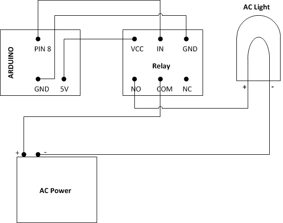
Circuit Design:
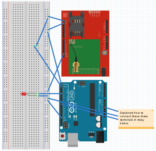
Connecting AC appliances through Relay connected
with ARDUNIO explained below.
ARDUINO Source Code:
Given below the code. Copy and Paste it in
ARDUINO Code explorer and burn the code in ARDUINO by selecting required COM
Port. Then Send Message from Sender Mobile as mentioned above. String inputString = ""; // a string to hold incoming data boolean stringComplete = false; // whether the string is complete
String incomingString =""; int startIndex = 0; int endIndex = 0;
int led1 = 4; int relay1 = 8;
void setup() { // initialize serial: Serial.begin(9600);
// prepare the digital output pins pinMode(led1, OUTPUT); pinMode(relay1, OUTPUT);
// initially all are off digitalWrite(led1, LOW); // reserve 200 bytes for the inputString: inputString.reserve(200);
//--Start: Send SMS -- Serial.print("AT+CMGF=1\r"); delay(1000);
//Serial.print("AT+CMGD=1,4\r"); // Deletes all SMS saved in SIM memory Serial.print("AT+CMGDA=\""); Serial.println("DEL ALL\""); delay(1000); Serial.print("AT+CMGS=\"+91XXXXXXXXXX\"\r"); //Number to which you want to send the sms
delay(1000); Serial.print("Test SMS - It Started Working1..\r"); //The text of the message to be sent delay(1000); Serial.write(0x1A); delay(1000);
Serial.print("AT+CNMI=2,2,0,0,0\r"); delay(1000); //--End: SMS-- }
void loop() { // print the string when a newline arrives: if (stringComplete && inputString!="") {
//Serial.print("AT+CMGL=ALL\r"); inputString.toLowerCase();
if(inputString=="@light on#") { digitalWrite(led1, HIGH); digitalWrite(relay1,0); } else if(inputString=="@light off#") { digitalWrite(led1, LOW); digitalWrite(relay1,1); } // Serial.println(inputString);
//Serial.println(incomingString);
Serial.print("AT+CMGDA=\""); Serial.println("DEL ALL\""); // Serial.print("AT+CMGD=1,4\r"); // Deletes all SMS saved in SIM memory delay(1000); // clear the string: inputString = ""; stringComplete = false; } }
void serialEvent() { if(stringComplete == false) { incomingString = Serial.readString(); if(incomingString!="") { startIndex = incomingString.indexOf("@"); endIndex = incomingString.indexOf("#");
if(startIndex>0 && endIndex>0) { inputString = incomingString.substring(startIndex,endIndex+1); stringComplete = true; } } } }
That’s all, Follow the steps to Turn ON/OFF
LEDs.
1. Burn
the ARDUINO code into ARDUINO.
2. Make
sure you have connected GSM Module and ARDUINO along with LED.
3. Make
sure the SIM present in GSM Module is working.
4. Send
Message from your mobile.
5. Experience it!!!
Note: Extra care should be taken when dealing with 240V, please
don't attempt if you are not confident. Please your suggestions/queries/experiences
to improve this article.
Hope this article gave an idea on how to control AC appliances
using Arduino, relays and GSM Module. Thanks for reading this article. |